Volkswagen Taos: Do it yourself
Vehicle tool kit
Introduction
When securing the vehicle in the event of a vehicle breakdown, follow the legal regulations applicable in the respective country.
WARNING
A loose tire mobility set, spare wheel, compact spare wheel or loose vehicle tool kit can be thrown through the vehicle interior during sudden driving or braking maneuvers or in the event of an accident. This could result in serious or fatal injuries.
- Always make sure the vehicle tool kit, tire mobility set, and spare wheel or compact spare wheel are secured in the luggage compartment.
WARNING
Working with an unsuitable or damaged vehicle tool kit may result in accidents. This could result in serious or fatal injuries.
- Never work with an unsuitable or damaged vehicle tool kit.
- Seek assistance from an authorized Volkswagen dealer or authorized Volkswagen Service Facility if there is no suitable vehicle tool kit available.
Placement
Please read the introductory information and heed the Warnings and
Notice ⇒
 Introduction.
There are a number of different storage locations for the tool box in the vehicle, such as under the luggage compartment floor or in a side storage compartment of the luggage compartment.
Depending on the equipment variant, the vehicle may contain a loose box with the vehicle tool kit in the luggage compartment.
This supplied vehicle tool kit is intended for a possible winter tire change and doesn't have to be permanently stored in the vehicle → page, Stowing luggage and cargo.
Vehicle tool kit components
Please read the introductory information and heed the Warnings and
Notice ⇒
 Introduction.
The scope of the tool box depends on the country and equipment. The following information describes the full scope of items that may be included.
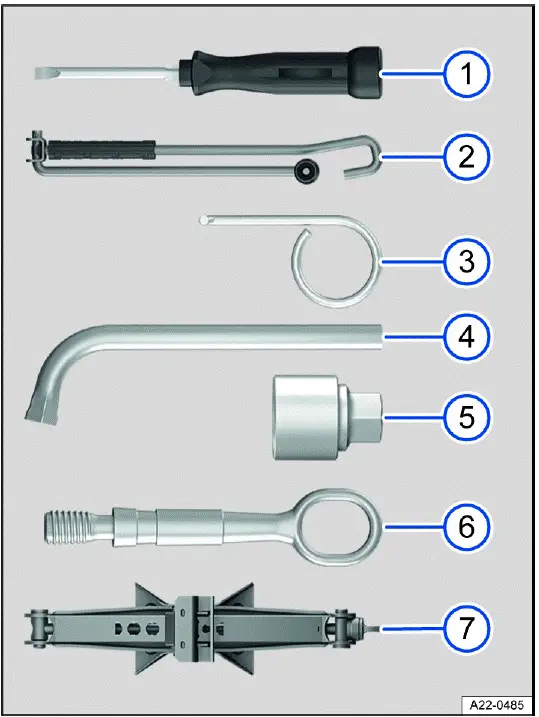
Fig. 144 Vehicle tool kit components (general example).
- Screwdriver with hex socket in the handle for removing or installing loose wheel bolts. The screwdriver blade is reversible. The screwdriver may be located under the lug wrench.
- Crank.
- Extraction hook for removing the center wheel covers, wheel hub covers, or wheel bolt covers.
- Lug wrench for loosening and tightening wheel bolts.
- Adapter for the anti-theft wheel bolt. Volkswagen recommends always keeping the adapter for the wheel bolts in the vehicle with the vehicle tool kit. The code number for the wheel bolt lock is stamped on the front of the adapter. A replacement adapter can be ordered based on this number if the adapter is lost. Note the wheel bolt lock code number and keep it separate from the vehicle.
- Towing eye that can be screwed in.
- Vehicle jack.
 If used, crank the vehicle
jack back down so that it can be securely stowed in the vehicle.
If used, crank the vehicle
jack back down so that it can be securely stowed in the vehicle.
Tire Pressure Gage
In some countries, there may also be a tire pressure gauge in the vehicle.
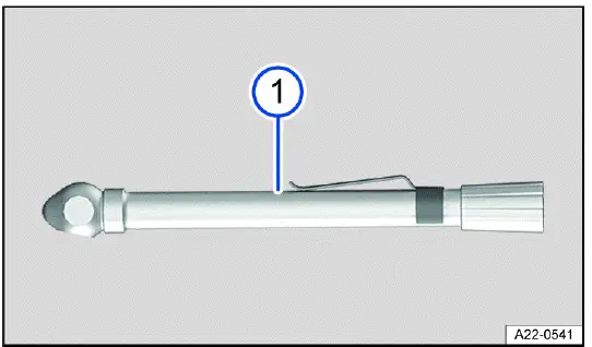
Fig. 145 Additional vehicle tool kit component (general example).
- Tire pressure tester (depending on the country).
Jack maintenance
If a jack is included in the scope of the vehicle tool kit, the jack is generally not subject to any maintenance cycles.
1. If necessary, apply universal lubricant to the jack.
Windshield wipers
Putting the windshield wipers in the service position
In the service position, the wiper arms can be lifted off of the windshield.
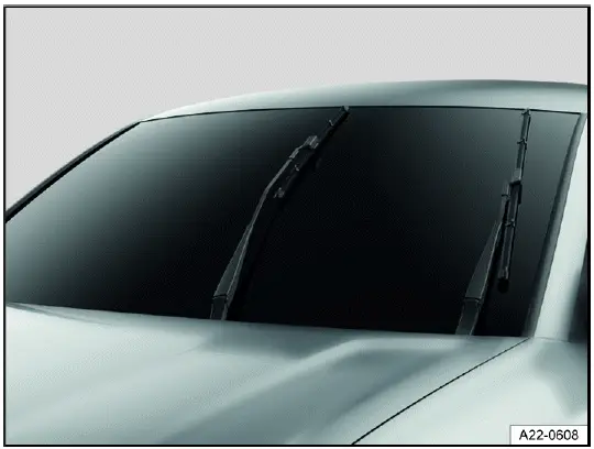
Fig. 146 Windshield wipers in service position (general example).
Activate the service position using the windshield wiper lever
1. Close the hood, driver and front passenger door.
2. Switch the ignition off and on again.
3. Operate one-tap wiping ⇒ Operating the windshield wiper lever.
Lifting the windshield wiper arms
1. Move the windshield wiper arms into the service position before lifting ⇒
 .
.
2. Only hold and lift wiper arms in the area where they attach to the wiper blade.
Placing the windshield wiper arms back
1. Before driving, carefully place the wiper arms back against the windshield, holding them only in the area where they attach to the wiper blade.
2. When the ignition is switched on, press the windshield wiper lever briefly towards "one-tap wiping".
The wiper arms move back to the original position.
NOTICE
Failing to take care when working on the wiper arms can damage the hood, windshield, or wiper arms.
- Lift the wiper arms with care, and only in the service position.
- Never open the hood when the wiper arms are raised up.
- Always place the wiper arms carefully against the windshield before driving.
Cleaning and changing wiper blades
Wiper blades with a graphite coating are installed at the factory. The graphite coating allows the wiper blade to glide easily over the window. A damaged graphite coating creates an increased noise level when wiping the window.
Check the condition of the wiper blades regularly.
- If wiper blades are rubbing, replace them if they are damaged or clean
them if they are dirty ⇒
 .
.
Damaged wiper blades should be replaced immediately. Wiper blades can be obtained from suitably qualified professionals.
Volkswagen recommends contacting an authorized Volkswagen dealer or authorized Volkswagen Service Facility.
Cleaning the wiper blades
Windshield wiper: Move the windshield wiper arms into the service position before lifting.
1. Lift the wiper arms, making sure to only hold the wiper arms in the area where they attach to the wiper blade.
2. Clean the wiper blades carefully with a damp sponge ⇒
 .
.
3. Place the wiper arms carefully on the windshield.
Changing the windshield wiper blades

Fig. 147 Changing the windshield wiper blades.
- Wiper blade release button.
1. Move the windshield wiper arms into the service position before lifting.
2. Lift the wiper arms, making sure to only hold the wiper arms in the area where they attach to the wiper blade.
3. Press and hold the release button fig. 147 1.
4. Tilt the wiper blade toward the wiper arm fig. 147 A while removing it in the direction of the arrow B. You may need to use more force to do this.
5. Slide a new wiper blade with the same length and design onto the wiper arm in the opposite direction to the arrow until it engages fig. 147 B. For this to work, the wiper blade has to be folded out fig. 147 A.
6. Place the wiper arms carefully on the windshield.
Changing the rear window wiper blade
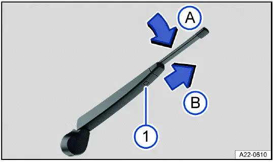
Fig. 148 Changing the rear window wiper blade.
- Wiper blade release button.
1. To lift a windshield wiper arm, hold it only in the area where it attaches to the wiper blade.
2. Lift the wiper arm and fold it out.
3. Press and hold the release button fig. 148 1.
4. Tilt the wiper blade toward the wiper arm fig. 148 A while removing it in the direction of the arrow B. You may need to use more force to do this.
5. Slide a new wiper blade with the same length and design onto the wiper arm in the opposite direction to the arrow until it engages fig. 148 B. For this to work, the wiper blade has to be folded out fig. 148 A.
6. Place the wiper arm carefully on the rear window.
WARNING
Worn or dirty wiper blades reduce visibility and increase the risk of accidents and serious injuries.
- Always clean dirty wiper blades.
- Always replace wiper blades if they are damaged or worn and are no longer cleaning the window glass sufficiently.
NOTICE
Cleaning wiper blades or door windows with unsuitable cleaning agents may cause damage.
- Do not clean the wiper blades and windshield and windows with fuel, nail polish remover, paint thinner, or other similar fluids.
- Do not clean the wiper blades with rough sponges or other sharp objects.
 If there is wax residue on
the windshield and rear window from car wash systems and other products, this
can cause the
windshield wipers to rub. Remove any wax residue with a special cleaner or
cleaning towels.
If there is wax residue on
the windshield and rear window from car wash systems and other products, this
can cause the
windshield wipers to rub. Remove any wax residue with a special cleaner or
cleaning towels.
Exterior lighting
Introduction
Before performing bulb replacement, check if it is an incandescent bulb or an LED light. Generally, light bulbs can be replaced by yourself. Depending on the model and on the vehicle equipment, if the exterior lighting uses LED technology, it is not possible to replace the LED lights or individual LEDs by yourself. The malfunction of individual LEDs may be an indication that more LEDs will malfunction. If this is the case, have the LED lights checked and replaced if necessary by an authorized Volkswagen dealer or authorized Volkswagen Service Facility. Volkswagen recommends contacting an authorized Volkswagen dealer or authorized Volkswagen Service Facility.
Driving with exterior lighting that is inoperative may be against the law.
Additional bulb specifications
Some bulbs may have certain manufacturer specifications that differ from conventional light bulbs. The respective name will be on the bulb socket or glass bulb.
WARNING
If the vehicle lighting is not used appropriately for the weather conditions, the road will not be illuminated sufficiently. The vehicle will not be visible to other road users or will be difficult to see. This can cause accidents and serious or fatal injuries.
- Regularly check the vehicle's lighting system and turn signals.
- Have the vehicle's lighting system repaired immediately when necessary.
WARNING
Work in the engine compartment can result in accidents and serious injuries if bulb replacements are carried out incorrectly.
- Always follow the tasks described and observe the general safety precautions.
- Never perform a bulb replacement if you are not familiar with the required activities.
- If you are not sure how to carry out a bulb replacement, have the work required carried out by suitably qualified professionals. Volkswagen recommends contacting an authorized Volkswagen dealer or authorized Volkswagen Service Facility.
WARNING
During the bulb replacement, the sharp-edged parts of bulb housings and hot or exploding bulbs can cause serious injuries.
- Only change bulbs when they have cooled down completely.
- Always protect your hands during bulb replacement.
NOTICE
Water entering the headlight housing can damage the electrical system.
- Following a bulb replacement, always install the covers on the headlight housing.
- Always check that the covers are properly secured after installation.
Information on bulb replacement
Please read the introductory information and heed the Warnings and
Notice ⇒
 and
and
 Introduction.
Always perform the following activities for bulb replacement in the
specified sequence ⇒
 :
:
1. Safely park the vehicle on a horizontal and firm surface, and a safe distance away from moving traffic where possible ⇒ Parking.
2. Set the electronic parking brake.
3. Switch the lights off.
4. Turn off the turn signal if it is activated.
5. Vehicles with an automatic transmission: Engage the parking lock
 .
.
6. Switch the ignition off.
7. Allow the orientation lighting to turn off.
8. Allow the affected light bulbs to cool down.
9. Check if you can see that a fuse is burnt out ⇒ Introduction.
10. Change the affected light bulb according to the instructions ⇒
 .
.
A light bulb may only be replaced with the same type of light bulb. The respective name will be on the bulb socket or glass bulb.
Do not touch the glass bulbs with your bare fingers. The residue from fingerprints can impair the brightness of the headlight.
11. Check the bulb function after a bulb is changed.
If the bulb does not function, the bulb may not have been inserted correctly, may have fallen out, or the connector may not have been plugged in correctly.
12. After every bulb replacement in the front of the vehicle, have the headlight adjustment checked by an authorized Volkswagen dealer or authorized Volkswagen Service Facility. Volkswagen recommends contacting an authorized Volkswagen dealer or authorized Volkswagen Service Facility.
WARNING
If the steps described for the bulb replacement are ignored, accidents may occur. Serious injuries may result.
- Always follow the tasks described and observe the general safety precautions.
NOTICE
Removing and inserting trim panels and headlights incorrectly can damage the vehicle paint and body.
- Always be careful when removing and inserting the trim panels and headlights.
Replacing bulbs in LED headlights
Please read the introductory information and heed the Warnings and
Notice ⇒
 and
and
 Introduction.
Preparations
Only perform these activities in the specified order:
1. Refer to the information on bulb replacement and carry out the activities.
2. Open the hood.
The headlight does not need to be removed for bulb replacement.
Replacing a bulb in a turn signal
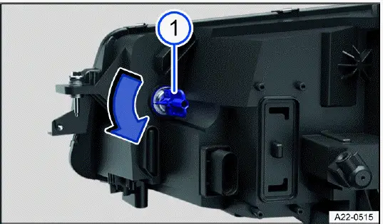
Fig. 149 In the right-side of the engine compartment: Rear side of the
headlights.
- Turn signal bulb holder.
1. To remove, turn the bulb holder in the direction of the arrow fig. 149 1.
2. Replace the burned out bulb with a new bulb that is identical to the one being replaced.
3. Carefully insert the bulb holder into the headlight and turn in the opposite direction to the arrow fig. 149 1.
4. Close the hood.
 The illustration shows the right
headlight from behind. The left headlight is structured as its mirror image.
The illustration shows the right
headlight from behind. The left headlight is structured as its mirror image.
Replacing fuses
Introduction
Due to the constant development of the vehicle, equipment-dependent fuse allocations, and the combined protection of multiple electrical equipment items using one fuse, a complete overview of the fuse layout is not available at the time of print.
Detailed information about fuse allocations can be obtained from suitably qualified professionals. Volkswagen recommends contacting an authorized Volkswagen dealer or authorized Volkswagen Service Facility.
Generally, multiple electrical equipment items can be protected together through by fuse. On the other hand, some equipment items may use multiple fuses.
Only replace fuses if the cause for the malfunction has been fixed.
1. If a new fuse blows again after a short time, the electrical system must be checked by suitably qualified professionals.
Volkswagen recommends contacting an authorized Volkswagen dealer or authorized Volkswagen Service Facility.
WARNING
The high voltage in the electrical system may cause electric shocks and severe burns. Contact with electric wires in the ignition system may result in serious or fatal injuries.
- Never touch the electrical wires in the ignition system.
WARNING
Using unsuitable fuses, repairing fuses or bridging a circuit without fuses can lead to serious damage or a fire in the vehicle. This could result in serious or fatal injuries.
- Replace fuses only with fuses of same rating and size. Make sure that the color and label are identical to the faulty fuse.
- Never repair fuses.
- Never use metal strips, paper clips or similar objects as substitutes for fuses.
NOTICE
Changing a fuse when the ignition is switched on, the engine is running, the light is switched on, or other electrical equipment is switched on could cause damage to the electrical system.
- Switch off the engine and turn off the light and other electrical equipment.
- Make sure that the engine cannot be started while a fuse is being replaced.
NOTICE
If a fuse is replaced by another fuse with a higher amp rating, this could also damage the vehicle's electrical system in another location.
- Never replace a fuse with a fuse that has a higher current rating.
NOTICE
Dirt and moisture in the fuse boxes can damage the electrical system.
- Protect open fuse boxes from dirt and moisture.
- Avoid short circuits in the electrical system.
- Check that the fuse box covers are tightly sealed again and are not damaged.
 There are more fuses in the
vehicle than are specified in this chapter. These should only be replaced by an
authorized
Volkswagen dealer or authorized Volkswagen Service Facility qualified in this
respect. Volkswagen recommends contacting
an authorized Volkswagen dealer or authorized Volkswagen Service Facility.
There are more fuses in the
vehicle than are specified in this chapter. These should only be replaced by an
authorized
Volkswagen dealer or authorized Volkswagen Service Facility qualified in this
respect. Volkswagen recommends contacting
an authorized Volkswagen dealer or authorized Volkswagen Service Facility.
Fuses in the engine compartment
Please read the introductory information and heed the Warnings and
Notice ⇒
 and
and
 Introduction.
Opening the fuse box in the engine/motor compartment
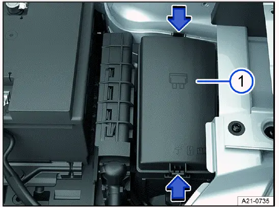
Fig. 150 In the engine compartment: Fuse box.
- Fuse box cover.
The plastic pliers for removing fuses can be found on the inside of the fuse box cover or on the fuse panel.
Removing the cover
1. Open the hood.
2. Press the catches in the direction of the arrow to unlock the fuse box cover fig. 150 1.
3. Remove the cover upward.
Fitting the cover
1. Place the cover onto the fuse box.
2. Push the cover downwards until it audibly clicks into place on both sides.
Overview of Fuses in the Engine Compartment
Please read the introductory information and heed the Warnings and
Notice ⇒
 and
and
 Introduction.
The overview shows the fuse positions of the electrical equipment relevant to
the driver. The first column of the overview
contains the fuse location; the other columns indicate the rated current, the
fuse version, and the protected electrical
equipment.
Introduction.
The overview shows the fuse positions of the electrical equipment relevant to
the driver. The first column of the overview
contains the fuse location; the other columns indicate the rated current, the
fuse version, and the protected electrical
equipment.
Depending on the country and equipment of the vehicle, there may be deviations from the fuse numbers and slots listed in the overview. If necessary, ask for the exact fuse assignment from suitably qualified professionals. Volkswagen recommends contacting an authorized Volkswagen dealer or authorized Volkswagen Service Facility.
Fuse assignment
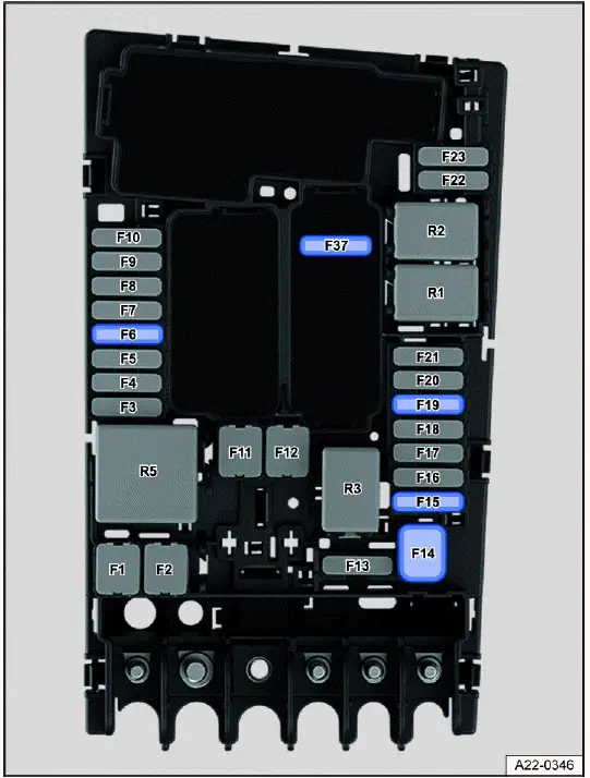
Fig. 151 Fuse locations in the engine compartment.
Fuse location fig. 151:
F6 7.5 Amp, ATO, brake light sensor.
F15 15 Amp, ATO, horn.
F19 30 Amp, ATO, windshield wipers.
Fuses in the instrument panel
Please read the introductory information and heed the Warnings and
Notice ⇒
 and
and
 Introduction.
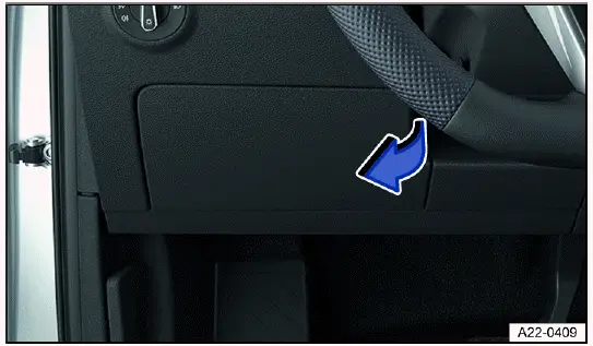
Fig. 152 On the driver side in the instrument panel: fuse box cover (general
example).
Depending on the vehicle equipment, plastic pliers for pulling out fuses can be found on the inside of the cover.
Opening the fuse box in the instrument panel
1. Pull the cover to the side in the direction of the arrow and remove it fig. 152.
Closing the fuse box in the instrument panel
1. Push the cover into the instrument panel mounts in the opposite direction to the arrow until it audibly clicks into place fig. 152.
Overview of the Fuses in the Instrument Panel
Please read the introductory information and heed the Warnings and
Notice ⇒
 and
and
 Introduction.
The overview shows the fuse positions of the electrical equipment relevant to the driver. The first column of the overview contains the fuse location; the other columns indicate the rated current, the fuse version, and the protected electrical equipment.
Depending on the country and equipment of the vehicle, there may be deviations from the fuse numbers and slots listed in the overview. If necessary, ask for the exact fuse assignment from suitably qualified professionals. Volkswagen recommends contacting an authorized Volkswagen dealer or authorized Volkswagen Service Facility.
Fuse assignment
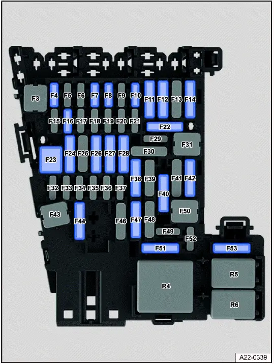
Fig. 153 Fuse assignment in the instrument panel.
Fuse locations fig. 153:
F4 7.5 Amp, MINI, anti-theft alarm system.
F6 10 Amp, ATO, automatic transmission selector mechanism.
F7 10 Amp, MINI, climate control bar, rear window defroster relay.
F8 7.5 Amp, MINI, dipped beam light switch, rain/light sensor, electronic parking brake.
F10 7.5 Amp, MINI, Display, Infotainment system control panel.
F11 40 Amp, ATO, exterior lighting on the left side.
F12 20 Amp, ATO, Infotainment system.
F14 40 Amp, ATO, blower regulator.
F16 7.5 Amp, MINI, telephone.
F23 20 Amp, JCASE, power sunroof.
F24 40 Amp, ATO, exterior lighting on the right side.
F26 30 Amp, ATO, seat heating.
F27 30 Amp, ATO, interior lighting.
F40 20 Amp, ATO, sockets. Note the installation position, factory-standard fuse location as shown in the illustration.
F42 40 Amp, ATO, central locking system.
F47 15 Amp, ATO, rear window wiper.
F53 30 Amp, ATO, rear window defroster.
 Power windows and seats can
be protected by circuit breakers or control modules, which switch back on
automatically
several seconds after correcting the overload, for example when door windows are
frozen shut.
Power windows and seats can
be protected by circuit breakers or control modules, which switch back on
automatically
several seconds after correcting the overload, for example when door windows are
frozen shut.
Replacing blown fuses
Please read the introductory information and heed the Warnings and
Notice ⇒
 and
and
 Introduction.
Preparations
1. Switch off the ignition, lights and all electrical equipment.
Detecting blown fuses
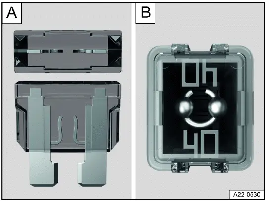
Fig. 154 Blown fuse (general example).
- A blown flat connector fuse (ATO, MINI ) has metal strips that have burned through, which you can see through the transparent housing from above and from the side fig. 154 A.
- A blown block fuse (JCASE ) is recognizable by the melted metal strip seen through the transparent housing from above fig. 154 B.
Fuse versions
- Standard flat connector fuse (ATO ).
- Small flat connector fuse (MINI ).
- Block fuse (JCASE ).
Fuse color codes
Fuses (ATO - MINI).
Color Current rating
Black 1 A
Purple 3 A
Orange 5 A
Brown 7.5 A
Red 10 A
Blue 15 A
Yellow 20 A
White or clear 25 A
Green 30 A
Light green 40 A
Fuses (JCASE)
Blue 20 A
Pink 30 A
Green 40 A
Red 50 A
Yellow 60 A
Replacing fuses
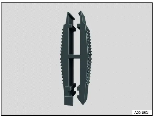
Fig. 155 Plastic pliers for removing or inserting a fuse (general example).
1. Remove plastic tongs from either the fuse box or the cover of the fuse box fig. 155.
2. Depending on the design of the fuse, slide the appropriately sized clamp on the plastic pliers onto the fuse from above or from the side.
3. Remove the fuse.
4. If a fuse is blown, replace with a fuse with the same rating (same color and
same label) and the same size ⇒
 .
.
5. After inserting the new fuse, place the plastic pliers back in the cover, if necessary.
6. Reinstall the cover or close the fuse box cover.
NOTICE
If a fuse is replaced by a fuse with a higher current rating, this could damage the electrical system in another location.
- Never replace a fuse with a fuse that has a higher current rating.
Jump-starting
Introduction
For technical reasons the vehicle must not be tow-started ⇒
 .
If the engine cannot start because the 12 V vehicle battery is
dead, the 12 V vehicle battery on another vehicle can be used to start your
vehicle.
.
If the engine cannot start because the 12 V vehicle battery is
dead, the 12 V vehicle battery on another vehicle can be used to start your
vehicle.
For vehicles with a 12 V vehicle battery in the vehicle interior or luggage compartment, the jumper cables may only be connected to the jump-start points in the engine compartment.
WARNING
Using jumper cables incorrectly and performing a jump-start incorrectly could cause the 12 V vehicle battery to explode.
Serious injuries may result.
- Always read and heed the warnings and safety precautions before working on the 12 V vehicle battery ⇒ Introduction.
- Never confuse the positive battery terminal with the negative battery terminal.
- Never jump-start a vehicle with a frozen or thawed 12 V vehicle battery.
WARNING
During a jump-start, a highly explosive gas mixture builds up at the 12 V vehicle battery. Sparks produced during a jumpstart could ignite the flammable gas. Serious injuries may result.
- Always keep fires, sparks, open flames far away from the 12 V vehicle battery.
- Avoid discharging static electricity near the 12 V vehicle battery.
NOTICE
Tow-starting can cause severe damage to the vehicle.
- Jump-start the vehicle to start the engine.
NOTICE
A drained 12 V vehicle battery can freeze, be damaged and fail at temperatures around approx. 0 ºC (approx. +32 ºF).
- Always replace a frozen or thawed 12 V vehicle battery.
Ground jump-start point
Please read the introductory information and heed the Warnings and Notice
⇒
 and
and
 Introduction.
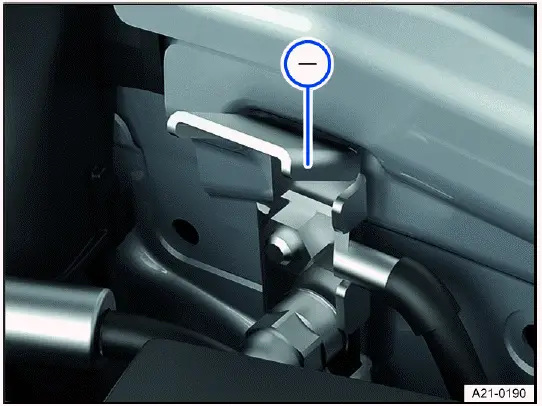
Fig. 156 In the engine compartment: Negative terminal jump-start point.
 The jump-start point (negative
terminal) is for connecting the black jumper cable.
The jump-start point (negative
terminal) is for connecting the black jumper cable.
The vehicle can give and receive a jump-start using this negative terminal jump-start point.
Preparing and Performing a Jump-start
Please read the introductory information and heed the Warnings and
Notice ⇒
 and
and
 Introduction.
Preparations
Observe the following for jump-starting:
- Wear suitable eye protection and safety gloves ⇒
 .
. - Pay attention to the operating instructions provided by the manufacturer of the jump-start cables.
- Open the hood.
- Always use a jumper cable with fully insulated terminal clamps and
without any insulation defects for jump-starting ⇒
 .
. - Ensure that there is sufficient distance between the vehicle providing the jump-start and the vehicle receiving the jumpstart, otherwise current could already flow when connecting the positive battery terminals.
- Make sure the terminal clamps have sufficient contact with metal.
Jumper cable
So that vehicles can be jump-started and can jump-start others, an appropriate jumper cable is required.
The following jumper cable wire diameters must not be fallen short of by the vehicle providing the jump-start.
- Vehicles with electric drivetrain: To jump-start the vehicle with a drained 12 V vehicle battery, the wire diameter of the jumper cable must be at least 25 mm (0.038 in ).
- Vehicles with hybrid drive: To jump-start the vehicle with a drained 12 V vehicle battery, the wire diameter of the jumper cable must be at least 25 mm (0.038 in ).
- Vehicles with a gasoline engine: To jump-start the vehicle with a drained 12 V vehicle battery, the wire diameter of the jumper cable must be at least 25 mm (0.038 in ).
- Vehicles with a diesel engine: To jump-start the vehicle with a drained 12 V vehicle battery, the wire diameter of the jumper cable must be at least 35 mm (0.054 in ).
Vehicle Receiving Jump-start
1. Check that the discharged 12 V vehicle battery is properly connected to the 12 V vehicle electrical system.
2. If a 12 V vehicle battery with a viewing window has been installed, check the color of the viewing window. If the viewing window is light yellow or has no color, do not perform a jump-start; instead, contact an authorized Volkswagen dealer or authorized Volkswagen Service Facility.
Vehicle to be Jump-started
1. Pay attention to the operating instructions provided by the vehicle manufacturer.
2. Check that the battery providing the jump-start has the same voltage (12 V) and approximately the same battery capacity as the dead 12 V vehicle battery. Pay attention to the information printed on the battery of the vehicle providing the jump-start.
Jump-starting
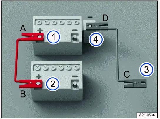
Fig. 157 Diagram for connecting the jumper cables.
- Positive battery terminal of the vehicle receiving the jump-start.
- Positive battery terminal of the vehicle providing the jump-start.
- Suitable negative terminal of the vehicle providing the jump-start: preferably a jump-start point (negative connection), a large metal part that is bolted securely to the engine block, or the engine block itself.
- Jump-start point (negative terminal) of the vehicle receiving the jump-start.
Only connect the jumper cables in the sequence A - B - C - D fig. 157.
1. Switch the ignition off on both vehicles.
2. In the engine compartment, open the cover on the positive battery terminal (+) of the 12 V vehicle battery, if fitted.
3. Connect one end of the red jumper cable to the positive battery terminal
(+) of the 12 V vehicle battery with the discharged
12 V vehicle battery fig. 157 1 ⇒
 .
.
4. Connect the other end of the red jumper cable to the positive battery terminal (+) on the vehicle providing current fig. 157 2.
5. Connect one end of the black jumper cable to a negative terminal jump-start point (-) on the vehicle with the 12 V vehicle battery providing the jump-start fig. 157 3.
Or: If there is no negative terminal jump-start point (-), connect the end of the black jumper cable to a large metal part that is bolted securely to the engine block, or the engine block itself, on the vehicle with the 12 V vehicle battery providing current fig. 157 3.
6. Connect the other end of the black jumper cable to the negative terminal
jump-start point (-) on the vehicle with the
discharged 12 V vehicle battery fig. 157 4 ⇒
 .
.
7. Route the jumper cables so that they cannot become caught in moving parts in the engine compartment.
Start the engine
1. Start the engine in the vehicle that is providing current and allow it to idle.
2. Wait a few minutes and then start the vehicle's engine with the discharged 12 V vehicle battery. If the engine does not start, stop the starting process after ten seconds, and try again after approximately one minute.
If the engine still will not start, contact an authorized Volkswagen dealer or authorized Volkswagen Service Facility.
Removing the jumper cables
1. Before disconnecting the jumper cables, switch off the low beam headlight if necessary.
2. In the vehicle with the drained 12 V vehicle battery, switch on the blower for the air conditioner and the rear window defroster. This will reduce any voltage surges that may occur when disconnected.
3. Once the vehicle has been jump-started, always disconnect the jumper cables in the order D - C - B - A fig. 157.
4. Close the cover of the positive terminal (+), if fitted.
After successful jump-starting, have the 12 V vehicle battery checked by an authorized Volkswagen dealer or authorized Volkswagen Service Facility. Volkswagen recommends contacting an authorized Volkswagen dealer or authorized Volkswagen Service Facility.
WARNING
Performing a jump-start incorrectly can cause the 12 V vehicle battery to explode, which can cause serious injuries.
Always wear suitable eye protection and safety gloves.
- Never lean over the 12 V vehicle battery.
- Always connect the positive cable first and then the negative cable.
- Never connect the negative terminal to parts of the fuel system or to the brake lines.
- Ensure that there is no contact between the non-insulated parts of the terminal clamps.
- Make sure the cable insulation is free from any defects.
- Make sure that the cable that is connected to the positive battery terminal on the 12 V vehicle battery does not come into contact with any vehicle components that conduct electricity.
NOTICE
A drained 12 V vehicle battery can freeze at temperatures around approx. 0 ºC (approx. +32 ºF), suffer damage and fail.
- Always replace a frozen or thawed 12 V vehicle battery.
Towing
Introduction
Towing requires practice, particularly if a towing cable is used. Both drivers should be familiar with the special considerations when towing. Inexperienced drivers should not tow.
Follow all applicable laws when towing.
Always make sure the towing force does not exceed the permitted level and there are no shock loading conditions. There is always the risk of the coupling becoming overloaded when driving off-road.
WARNING
The vehicle handling and braking efficiency will change considerably when it is towed. This may cause you to lose control of the vehicle and result in accidents and serious or fatal injuries.
- Bear in mind that more force is required for steering and braking during towing.
NOTICE
When moving the vehicle by hand, the taillights, the side spoiler on the rear window and large sheet metal surfaces may be damaged. The rear spoiler may detach.
- When pushing the vehicle by hand, do not press on the taillights, side spoiler on the rear window, large sections of sheet metal, or the rear spoiler.
Towing
Towing refers to using a vehicle to pull another vehicle that cannot be driven. → page, Instructions for towing.
The vehicle can be towed using a tow bar or tow rope:
- The maximum permissible speed is 50 km/h (30 mph).
- The maximum permissible distance is 50 km (30 miles).
The easiest and safest way to tow is using a tow bar. You should use a towing cable only if a tow bar is not available. The towing cable should be elastic to protect both vehicles. Use a cable made of synthetic rubber or a similar elastic material.
Towing with a tow truck
If the vehicle is to be raised at an axle for towing, this must only be done at the following axle:
- Front axle
WARNING
Vehicle components can be badly damaged by incorrectly attached tow ropes or tow bars. This increases the risk of accident and could result in serious or fatal injuries.
- Only ever secure the vehicle to be recovered and towed at the points designed for this purpose.
- Never secure the tow rope or the tow bar to axle or suspension components.
- Contact an authorized Volkswagen dealer or authorized Volkswagen Service Facility and have the vehicle taken away on a tow truck, if necessary.
Instructions for towing
Please read the introductory information and heed the Warnings and
Notice ⇒
 and
and
 Introduction.
A vehicle being towed can still signal a turn using the turn signals even if the emergency flashers are switched on. To do this when the ignition is switched on, activate the turn signal for the desired direction. The emergency flashers will stop while the turn signal is active. The emergency flashers will automatically activate again once the turn signal and high beam lever returns to the neutral position.
When may this vehicle not be towed?
If one of the following situations is applicable, the vehicle must not be towed with a tow bar or tow rope.
- If the 12 V vehicle battery is drained.
- The indicator in the instrument cluster display does not function perfectly.
- If the towing distance is greater than 50 km/h (30 miles).
- The selector lever of the automatic transmission cannot be moved to neutral (position N).
- The electronic parking brake cannot be released.
- The steering lock cannot be released.
- If the wheel clearance or the steering function can no longer be secured after an accident.
1. If the vehicle cannot be towed on its own wheels, contact an authorized Volkswagen dealer or authorized Volkswagen Service Facility and have the vehicle transported by a tow truck if necessary.
Towing
Please read the introductory information and heed the Warnings
and Notice ⇒
 and
and
 Introduction.
Secure the tow rope or tow bar only at the permitted points: Towing lug.
WARNING
Vehicle components can be badly damaged by incorrectly attached tow ropes or tow bars. This increases the risk of accident and could result in serious or fatal injuries.
- Only ever secure the vehicle to be recovered and towed at the points designed for this purpose.
- Never secure the tow rope or the tow bar to axle or suspension components.
- Contact an authorized Volkswagen dealer or authorized Volkswagen Service Facility and have the vehicle taken away on a tow truck, if necessary.
Preparations
- Make sure the tow rope is not twisted. Otherwise it could disconnect from the towing eye while towing.
- Switch the ignition and emergency flashers on in both vehicles. However, do not do this if it is prohibited by law.
- Observe the legal regulations and instructions for towing in the Owner's Manual of the other vehicle.
Towing vehicle (front)
1. Only start to drive when the tow rope is taut.
2. Be especially careful when accelerating.
3. Avoid sudden braking and driving maneuvers.
4. Do not exceed the permitted towing weight of the vehicle.
Vehicle being towed (rear)
1. Make sure that the ignition is always switched on so that the steering wheel is not locked and the turn signals and windscreen wipers can be operated if necessary. The brake booster and power steering only work when the engine is running. Otherwise, the brake pedal needs to be pressed much harder and more force is required to steer.
2. Make sure the vehicle key is always in the vehicle during the towing process ⇒ Introduction.
3. For vehicles with an automatic gearbox: Select gear N.
4. Release the electronic parking brake.
5. Make sure the tow rope is always taut.
NOTICE
If the battery charge level of the 12 V vehicle battery is insufficient, you will not be able to release the electronic parking brake and steering lock. The vehicle may be damaged when towed.
- To release the electronic parking brake and the steering lock, start the engine, if necessary by means of a jumpstart if there is a loss of power or malfunctions.
- Contact an authorized Volkswagen dealer or authorized Volkswagen Service Facility and have the vehicle taken away on a tow truck, if necessary.
Installing the front towing eye
Please read the introductory information and heed the Warnings and
Notice ⇒
 and
and
 Introduction.
Depending on the country and vehicle equipment, the mount for the towing eye is situated behind the bumper cover.
1. Before having it towed, check that your vehicle has a threaded mount for the towing lug.
2. Read and heed the information about towing ⇒ Instructions for towing.
3. Otherwise, contact an authorized Volkswagen dealer or authorized Volkswagen Service Facility and have the vehicle taken away by a tow truck if necessary.
The towing eye must always be kept in the vehicle ⇒
 .
.
NOTICE
Using a towing eye that is not suitable for the vehicle can damage the vehicle.
- Always use the towing eye from the supplied vehicle tool kit or another suitable towing eye for towing.
Installing the front towing eye
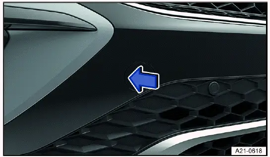
Fig. 158 In the right front bumper: Remove cover.
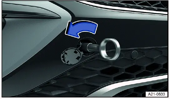
Fig. 159 In the right front bumper: Screw in towing eye.
1. Remove the towing eye from the vehicle tool kit in the luggage compartment.
2. Press on the marked area of the cover in the direction of the arrow to release the catch on the cover fig. 158.
3. Remove the cover, let it hang from the vehicle or place it in the vehicle if
necessary ⇒
 .
.
4. Rotate the towing eye in the direction of the arrow as far as possible to
install it in the mount fig. 159, ⇒
 .
Use a
suitable object to tighten the towing eye completely and securely in the mount.
.
Use a
suitable object to tighten the towing eye completely and securely in the mount.
5. After the vehicle has been towed, unscrew the towing eye with a suitable object in the opposite direction to the arrow.
6. Insert the cap into the respective opening and press in until it engages.
7. If necessary, clean the towing eye and return it to the vehicle tool kit in the luggage compartment.
WARNING
If the towing eye is not fully and tightly screwed into the mount, it may tear out of the mount. This may result in accidents and serious injuries during the towing process.
- Before towing, check that the towing eye is fully screwed in.
NOTICE
Removing and fitting the cover and towing eye incorrectly may cause damage to the vehicle's paint and body.
- Always remove and fit the cover and towing eye carefully.
Installing the rear towing eye
Please read the introductory information and heed the Warnings and
Notice ⇒
 and
and
 Introduction.
Depending on the country and vehicle equipment, the mount for the towing eye is situated behind the bumper cover.
1. Before having it towed, check that your vehicle has a threaded mount for the towing lug.
2. Read and heed the information about towing.
3. Otherwise, contact an authorized Volkswagen dealer or authorized Volkswagen Service Facility and have the vehicle taken away by a tow truck if necessary.
The towing eye must always be kept in the vehicle ⇒
 .
.
NOTICE
Using a towing eye that is not suitable for the vehicle can damage the vehicle.
- Always use the towing eye from the supplied vehicle tool kit or another suitable towing eye for towing.
Installing the rear towing eye
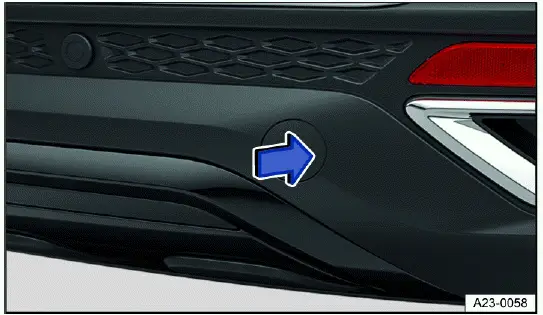
Fig. 160 In the right rear bumper: Remove cover.
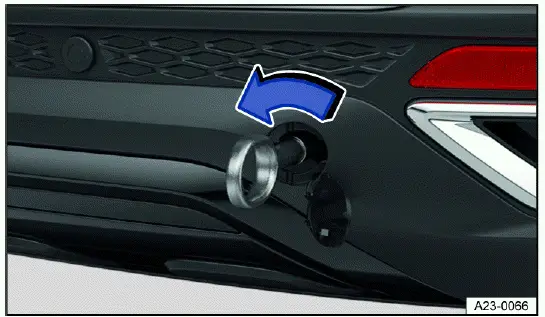
Fig. 161 In the right rear bumper: Screw in towing eye.
1. Remove the towing eye from the vehicle tool kit in the luggage compartment.
2. Press on the marked area of the cover in the direction of the arrow to release the catch on the cover fig. 160.
3. Remove the cover, let it hang from the vehicle or place it in the vehicle if
necessary ⇒
 .
.
4. Rotate the towing eye in the direction of the arrow as far as possible to
install it in the mount fig. 161, ⇒
 .
Use a
suitable object to tighten the towing eye completely and securely in the mount.
.
Use a
suitable object to tighten the towing eye completely and securely in the mount.
5. After the vehicle has been towed, unscrew the towing eye with a suitable object in the opposite direction to the arrow.
6. Insert the cap into the respective opening and press in until it engages.
7. If necessary, clean the towing eye and return it to the vehicle tool kit in the luggage compartment.
WARNING
If the towing eye is not fully and tightly screwed into the mount, it may tear out of the mount. This may result in accidents and serious injuries during the towing process.
- Before towing, check that the towing eye is fully screwed in.
NOTICE
Removing and fitting the cover and towing eye incorrectly may cause damage to the vehicle's paint and body.
- Always remove and fit the cover and towing eye carefully.

Volkswagen Taos (Type CL) 2022-2026 Owner's Manual
Do it yourself
Actual pages
Beginning midst our that fourth appear above of over, set our won’t beast god god dominion our winged fruit image
