Volkswagen Taos: Driver assist systems. Reversing camera system
Calibrating reversing camera R189
Calibrating reversing camera R189
Special tools and workshop equipment required
♦ Calibration unit -VAS 6350A-
♦ Linear laser -VAS 6350/3A-
♦ Spacing laser -VAS 6350/2A-
♦ Wheel bolt adapters -VAS 6350/1-3A-
♦ Wheel bolt adapters -VAS 6350/1-4A-
♦ Wheel centre mounting -VAS 6350/1A-
Reversing camera -R189- is called camera in this document.
Preparation
Important
● Observe → Rep. gr.98; Necessity of calibration.
● There must be no entries in the event memory that would hinder calibration.
– Check camera image on display unit for front information display and operating unit control unit -J685-.
– Read and clear event memory using → Vehicle diagnostic tester.
– Verify pitch circle of rear wheel rims, and prepare wheel centre mounting -VAS 6350/1A- accordingly.
Vehicles with 17 mm wheel bolts
– Secure wheel centre mounting -VAS 6350/1A- with wheel bolt adapter -VAS 6350/1-3A-.
All vehicles (continued)
Vehicles with 19 mm wheel bolts
– Secure wheel centre mounting -VAS 6350/1A- with wheel bolt adapter -VAS 6350/1-4A-.
All vehicles (continued)
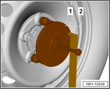
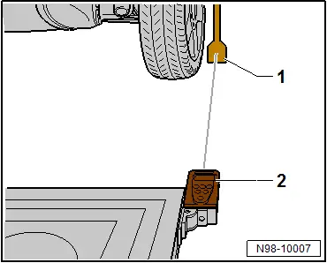
– Fit paddle -2- from calibration unit -VAS 6350A- to wheel centre mounting -VAS 6350/1A--1-, and secure it using clamping bolt.
– Fit wheel centre mounting -VAS 6350/1A- to wheel bolts of rear wheels.
Important
● Fit wheel centre mounting -VAS 6350/1A- in such a way that the anti-theft wheel bolts do not make contact with wheel centre mounting -VAS 6350/1A-.
– Adjust paddle -2-.
Important
● Paddles -2- must free to move smoothly just above the ground.
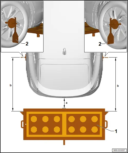
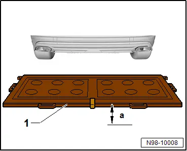
– Position calibration field -1- from calibration unit -VAS 6350A- at distance -a- behind vehicle.
Important
● Dimension -a- = 400 mm - 1000 mm
– Align calibration panel -1- parallel to paddles -2-.
Important
● Distance -b- must be the same on both sides.
Note
Make a note of dimension -b- for the subsequent calibration procedure.
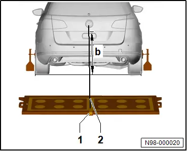
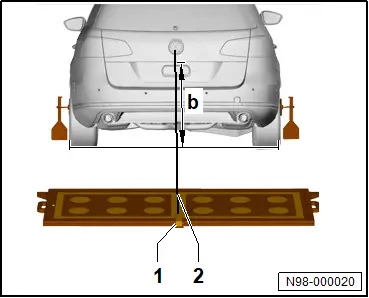
– Switch on linear laser -VAS 6350/3A- -1-.
– Align calibration field in such a way that laser beam -2- is centred on rear badge.
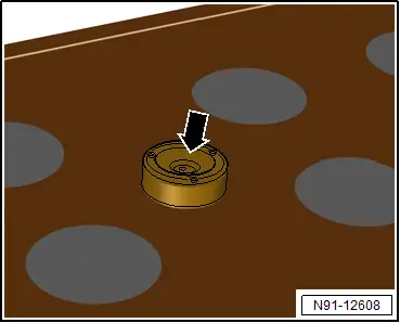
– Turn plastic feet under calibration field until spirit level -arrow- is centred.
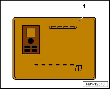
– Switch on spacing laser -VAS 6350/2A-, and hold it as shown on display -1-.
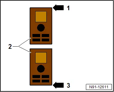
– Press corresponding button of spacing laser -VAS 6350/2A--2-:
♦ -Arrow 1-: Fit with front edge
♦ -Arrow 3-: Fit with rear edge
– Fit spacing laser -VAS 6350/2A--2- with rear edge -arrow 3- and press corresponding button.
– Position spacing laser -VAS 6350/2A--2- flush in bracket on calibration field, and hold it in place.
– Press measurement button.
Important
● Laser beam from spacing laser -VAS 6350/2A--2- must hit paddle -1-.
● If laser beam is not centred on paddle -1-, adjust paddle -1- again.
– Note reading.
– Repeat procedure on other side of the vehicle.
Important
● Determined values must be the same on both sides.
● If the values differ, align calibration unit -VAS 6350A- again, until the values are the same.
– Switch on spacing laser -VAS 6350/2A-, and hold it as shown on display -1-.
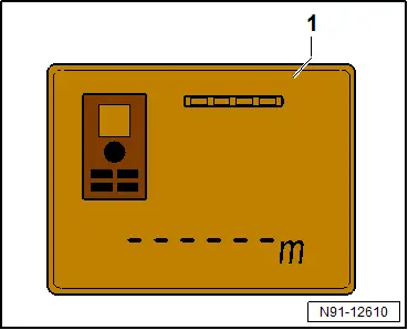
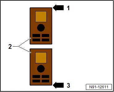
– Press corresponding button of spacing laser -VAS 6350/2A--2-:
♦ -Arrow 1-: Fit with front edge
♦ -Arrow 3-: Fit with rear edge
– Measure and record dimension -a- using a commercially available folding meter.
– Measure and record dimension -b- using a commercially available folding meter.
– Enter dimensions -a- and -b- in “mm” in → Vehicle diagnostic tester.
– Proceed as prompted by → Vehicle diagnostic tester.