Volkswagen Taos: Rear suspension, drive shaft. Rear axle
- Overview of fitting locations – rear axle
- Removing and installing rear axle
- Lowering rear axle, front section
- Lowering rear axle, rear section
- Securing vehicle to support arms of lifting platform
Overview of fitting locations – rear axle
Overview of fitting locations – rear axle
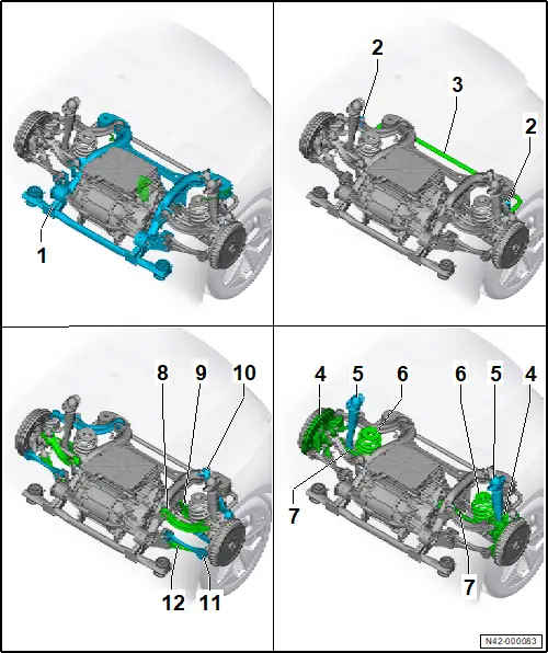
1 - Subframe
❏ → Rep. gr.42; Assembly overview – subframe
❏ → Rep. gr.42; Taking up weight of subframe using scissor-type assembly platform
❏ → Rep. gr.42; Removing and installing rear axle
2 - Coupling rod
❏ → Rep. gr.42; Assembly overview – anti-roll bar
❏ → Rep. gr.42; Removing and installing coupling rod
3 - Anti-roll bar
❏ → Rep. gr.42; Assembly overview – anti-roll bar
❏ → Rep. gr.42; Removing and installing anti-roll bar
4 - Wheel bearing housing
❏ → Rep. gr.42; Assembly overview – wheel bearing
❏ → Rep. gr.42; Removing and installing wheel bearing housing
5 - Shock absorbers
❏ → Rep. gr.42; Assembly overview – shock absorber
❏ → Rep. gr.42; Removing and installing shock absorber
6 - Spring
❏ → Rep. gr.42; Assembly overview – spring
❏ → Rep. gr.42; Removing and installing spring
7 - Drive shaft
❏ → Rep. gr.42; Assembly overview – drive shaft
❏ → Rep. gr.42; Removing and installing drive shaft
8 - Upper link (front)
❏ → Rep. gr.42; Assembly overview – suspension link
❏ → Rep. gr.42; Removing and installing upper front suspension link
9 - Spring control arm
❏ → Rep. gr.42; Assembly overview – spring control arm
❏ → Rep. gr.42; Removing and installing spring control arm
10 - Upper rear suspension link
❏ → Rep. gr.42; Assembly overview – suspension link
❏ → Rep. gr.42; Removing and installing upper rear suspension link
11 - Track rod
❏ → Rep. gr.42; Assembly overview – track rod
❏ → Rep. gr.42; Removing and installing track rod
12 - Lower suspension link
❏ → Rep. gr.42; Assembly overview – suspension link
❏ → Rep. gr.42; Removing and installing lower suspension link
Removing and installing rear axle
Removing and installing rear axle
Special tools and workshop equipment required
♦ scissor-type assembly platform -VAS 6131B-
♦ tensioning strap -T10038-
Removing
– Remove motor → Rep. gr.10; Removing and installing rear motor; Removing rear motor.
– Remove springs → Rep. gr.42; Removing and installing springs.
– Remove rear wheel housing liners → General body repairs, exterior; Rep. gr.66; Wheel housing liner; Removing and installing rear wheel housing liner.
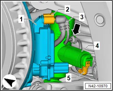
– Disconnect electrical connector -2- on left parking brake motor -V282- and on right parking brake motor -V283- -1-.
Vehicles with adaptive chassis control
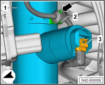
– Disconnect electrical connector -3- on rear left shock absorber damping adjustment valve -N338- and on rear right shock absorber damping adjustment valve -N339-.
– Pull electrical wire off retainer on shock absorber -2- on both sides of vehicle -arrow-.
All vehicles (continued)
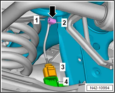
– Disconnect electrical wire -3- on rear left vehicle level sender -G76- -4-.
– Pull off electrical wire -2- on rear axle -1- -arrow-.
– Pull electrical wire -4- off retainer -2-.
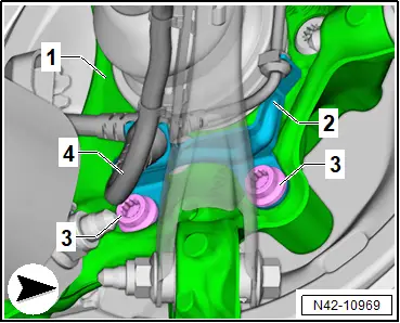
– Unclip retainer -1- for electrical wire -2- from lower suspension link -3-.
– To do this, press together locking lugs of retainer -1- at inside of lower suspension link -3-.
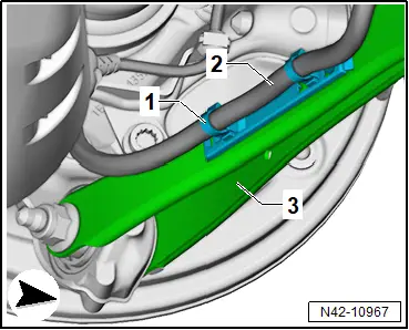
– Pull electrical wire -3- off retainer -4- on both sides of vehicle.
– Unclip electrical wire -3- from rear axle -1- on both sides of vehicle -2-.

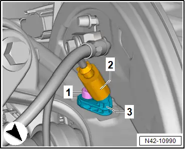
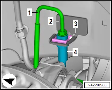
– Disconnect electrical connector -2- on rear left speed sensor -G46- and on rear right speed sensor -G44- -3-.
– Pull retaining clip -3- off brake hose -4- on both sides of vehicle.
– Unscrew brake line -1- on both sides of vehicle.
– Pull brake hose -4- out of retainer -2- on both sides of vehicle.
– Unclip electrical wire -3- from retainer -1- on right side of vehicle -arrows-.
– Unclip electrical wire -6- from retainer -4- on left side of vehicle -arrow-.
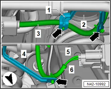
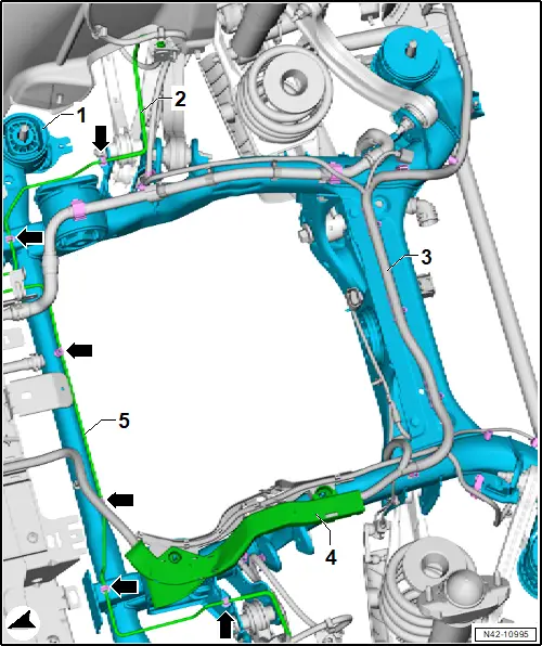
For greater clarity, the illustration shows the rear axle from above.
– Completely detach electrical wire -3- on rear axle -1-, and move it aside.
– Unclip brake lines -5- on rear axle -1- from retainers -arrows-.
– Pull cable guide -4- upwards off rear axle -1-.
– Secure electrical wire and brake lines to vehicle using suitable workshop materials.
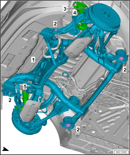
– → Rep. gr.42; Fix subframe in position.
– Unscrew bolts -3- for shock absorbers -4- and -5-.
– → Rep. gr.42; Take up weight of subframe using scissor-type assembly platform.
 NOTICE
Risk of lines becoming damaged due to limited space.
– When lowering, ensure sufficient clearance to brake lines and electrical wiring.
– Lower subframe with attachments using scissor-type assembly platform -VAS 6131B-.
– Use a tensioning strap -T10038- to secure subframe to scissor-type assembly platform -VAS 6131B-.
– Lower subframe with attachments further using scissor-type assembly platform -VAS 6131B-.
Installing
Install in reverse order of removal, observing the following:
– Carry out required function/functions using → Vehicle diagnostic tester → Rep. gr.00; Access to diagnoses.
– → Rep. gr.44; When does wheel alignment have to be checked?
Tightening torques
♦ → Rep. gr.42; Assembly overview – subframe
♦ → Rep. gr.42; Assembly overview – shock absorber
Lowering rear axle, front section
Lowering rear axle, front section
Special tools and workshop equipment required
♦ engine and gearbox jack -VAS 6931-
♦ gearbox support -T10337-
– Remove rear underbody cladding → General body repairs, exterior; Rep. gr.66; Underbody cladding; Removing and installing rear underbody cladding.
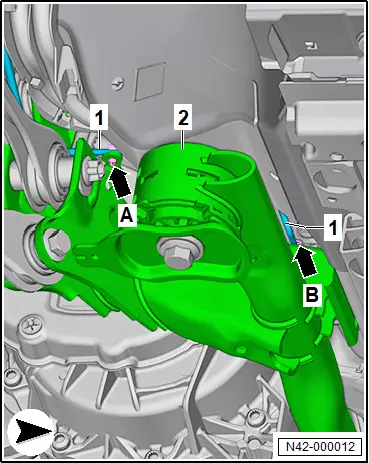
– Unclip brake line -1- on right side of subframe -2- -arrow A- and -arrow B-.
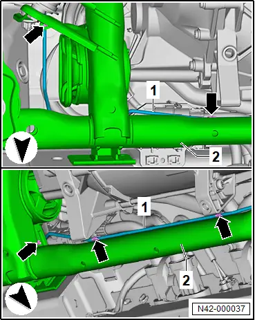
– Unclip brake line -1- on left side of subframe -2- -arrows-.
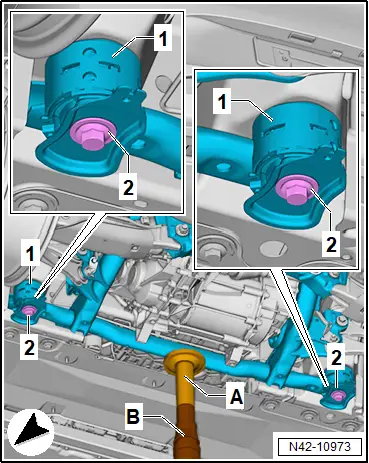
– Fit gearbox support -T10337- -A- onto engine and gearbox jack -VAS 6931- -B-.
– Position gearbox support -T10337- -A- on subframe -1-.
– Support subframe -1- with engine and gearbox jack -VAS 6931- -B-.
– Unscrew bolts -2- from subframe -1- on both sides of vehicle.
 NOTICE
Risk of damage to electrical wires, hoses and connections!
– Do not lower subframe any further than specified.
– When lowering, make sure not to damage any components.
– Lower subframe -1- approx. 35 mm.
Installing
Install in reverse order of removal, observing the following:
Vehicles with intermediate plates on front mountings on subframe
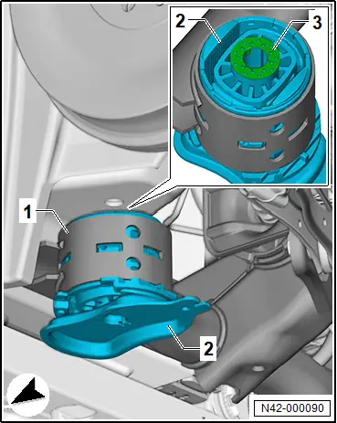
– Check if intermediate plate -1- is fitted between body and mounting.
Important
● There may be no intermediate plates -1- fitted on front subframe mounting -4- (fluted surface -3-).
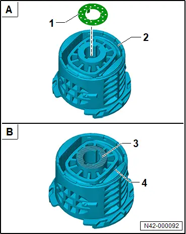
– Renew intermediate plate -3-.
Important
● Intermediate plates -3- must be fitted on both sides of vehicle.
– Insert intermediate plates -3- with locking lugs into front subframe mounting -2-.
All vehicles (continued)
Tightening torques
♦ → Rep. gr.42; Assembly overview – subframe
Lowering rear axle, rear section
Lowering rear axle, rear section
Special tools and workshop equipment required
♦ engine and gearbox jack -VAS 6931-
♦ gearbox support -T10337-
– Remove rear underbody cladding → General body repairs, exterior; Rep. gr.66; Underbody cladding; Removing and installing rear underbody cladding.
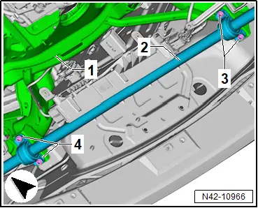
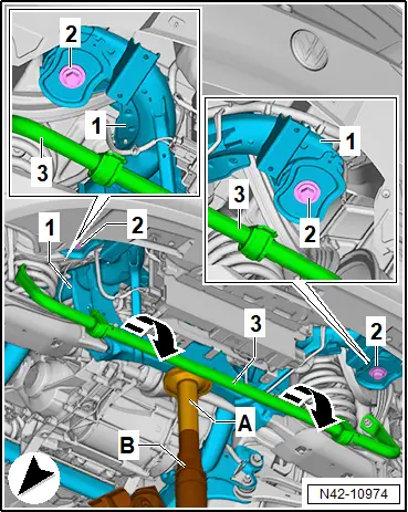
– Unscrew bolts -3- and -4- for anti-roll bar -2- on subframe -1-. Hold anti-roll bar when doing this.
– Detach anti-roll bar from subframe, and swing it downwards.
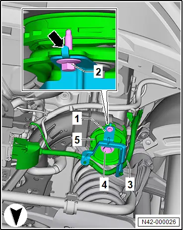
– Unscrew bolt -2- from subframe mounting on rear right -5-.
– Lay aside bracket -1- with electrical wire -3-.
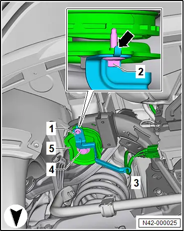
– Unscrew bolt -2- from subframe mounting on rear left -5-.
– Lay aside bracket -1- with electrical wire -3-.
– Fit gearbox support -T10337- -A- onto engine and gearbox jack -VAS 6931- -B-.
– Position gearbox support -T10337- -A- on subframe -1-.
– Support subframe -1- with engine and gearbox jack -VAS 6931- -B-.
– Unscrew bolts -2-.
 NOTICE
Risk of damage to electrical wires, hoses and connections!
– Do not lower subframe any further than specified.
– When lowering, make sure not to damage any components.
– Lower subframe -1- by 35 mm.
Installing
Install in reverse order of removal, observing the following:
Tightening torques
♦ → Rep. gr.42; Assembly overview - subframe
Securing vehicle to support arms of lifting platform
Securing vehicle to support arms of lifting platform
Special tools and workshop equipment required
♦ tensioning strap -T10523-
Removal and installation are described for the left side of vehicle as an example.
Securing for work on suspension links:
– Remove rear centre underbody cladding → General body repairs, exterior; Rep. gr.66; Underbody cladding; Removing and installing rear centre underbody cladding.
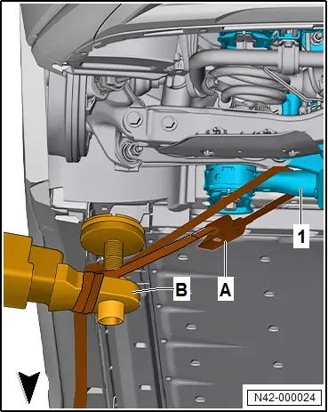
– Wrap tensioning strap -T10523- -A- support arms of lifting platform -B- on both sides of vehicle.
 NOTICE
Risk of damage to lines.
– Make sure that no brake lines, electrical wires, hoses or connections are trapped or put under tension.
– Lay tensioning strap -T10523- -A- around rear axle -1-.
– Insert end of tensioning strap into ratchet of tensioning strap -T10523- -A-.
– Tension the tensioning strap -T10523- -A-.
All vehicles (continued)
Securing for work on rear axle and to remove rear axle:
– Join three tensioning straps -T10523- to each other.
 NOTICE
Risk of damage to the vehicle if protective measures are insufficient.
– Cover paintwork and components using suitable workshop materials to protect them against damage.
– Make sure that no brake lines, electrical wires, hoses and connections are damaged when routing the tensioning straps.
– Position ratchets of tensioning strap so that they do not cause damage and can be actuated.
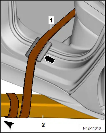
– Open rear doors on both sides of vehicle.
– Route tensioning strap -T10523- -1- through vehicle and around lifting platform.
– Wrap tensioning strap -T10523- -1- around support arms -2- of lifting platform on both sides of vehicle.
– Route tensioning strap -T10523- -1- beneath vehicle.
– Insert end of tensioning strap into ratchet of tensioning strap -T10523- -1-.
– Tension the tensioning strap -T10523- -1-.